
I have alot documents in my collection that are not shown on my vitessesteve.co.uk website. I have copies of many Triumph Vitesse owners handbooks.
You can view and download this handbook.
I have alot documents in my collection that are not shown on my vitessesteve.co.uk website. I have copies of many Triumph Vitesse owners handbooks.
You can view and download this handbook.

You can view and download the french language version of Triumph Herald 1200, 1250, Vitesse and Spitfire workshop manual
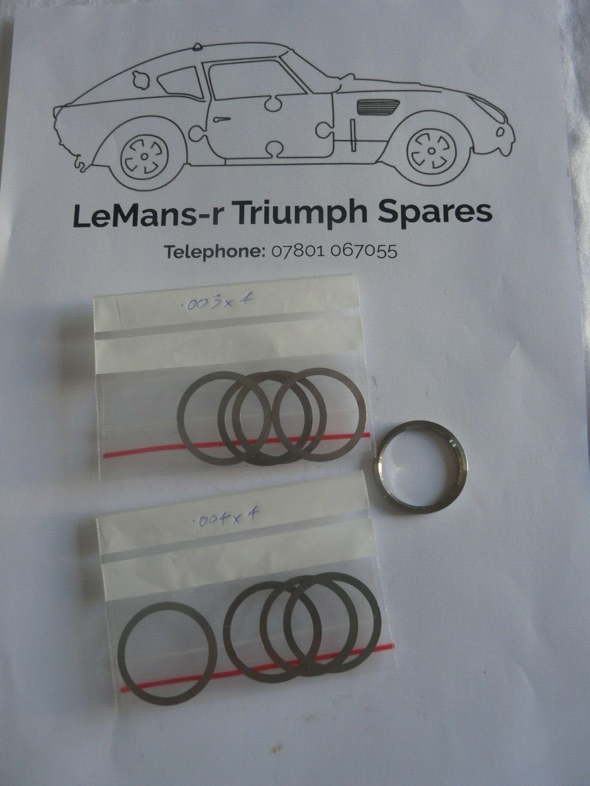
I was very pleased to track down a supply of shims to rebuild the rear hubs on my Triumph Vitesse.
Do you remember Jigsaw Racing? Well their workshop may have closed down but you can still buy stuff via their eBay store.
Now I just need to get my workshop built so my Vitesse can receive some long delayed attention.
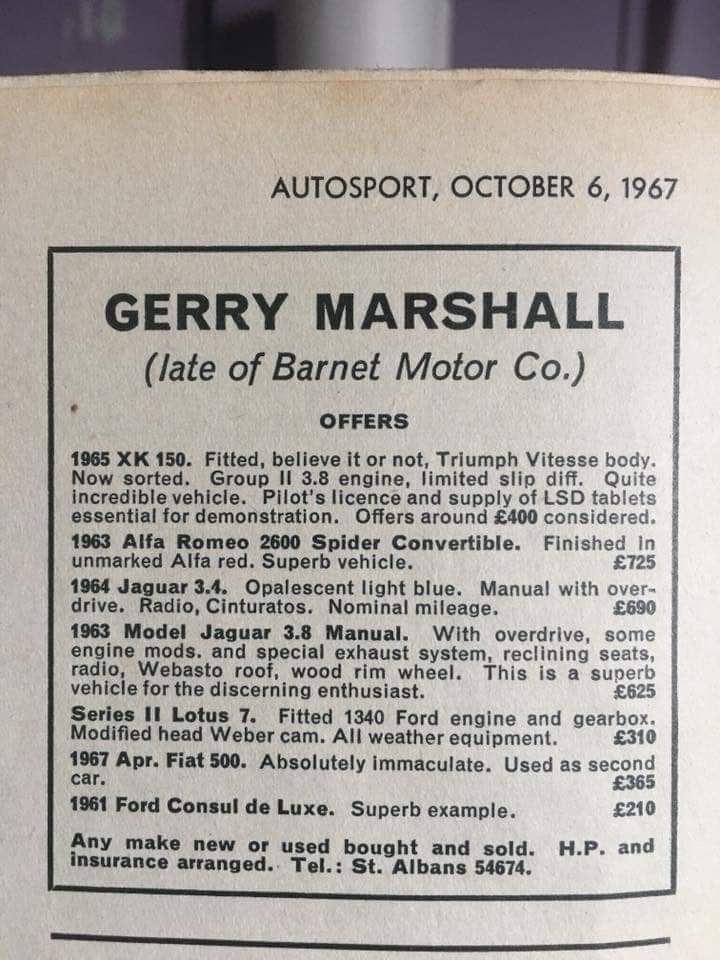
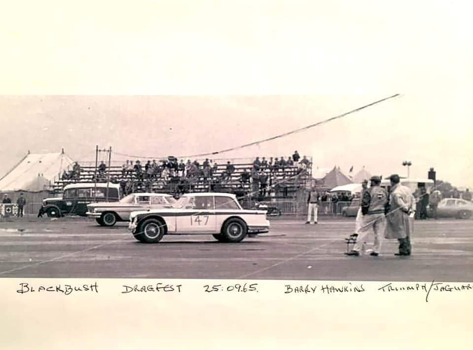
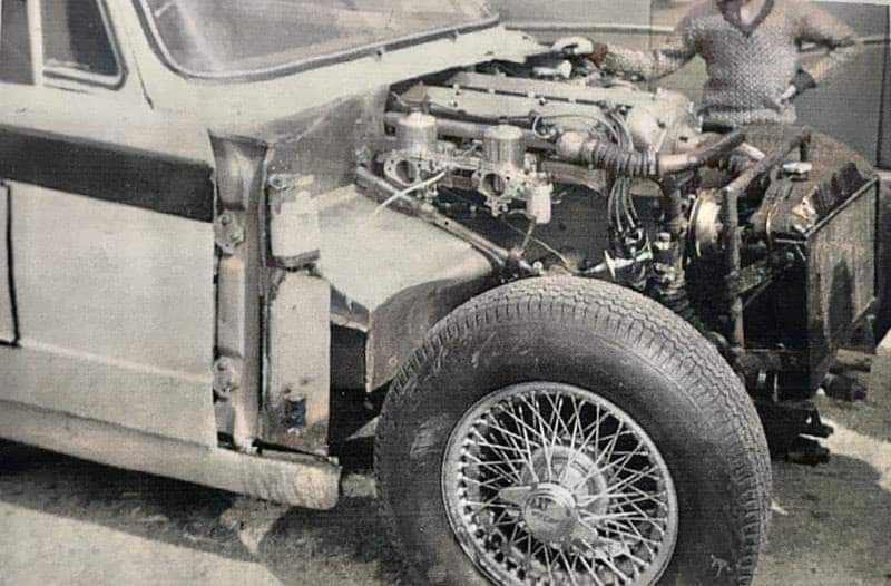
People have been tuning and modifying the Triumph Vitesse for many years. Hot Car magazine May 1969 featured a Vitesse that had a Jaguar 3.8 engine in it.
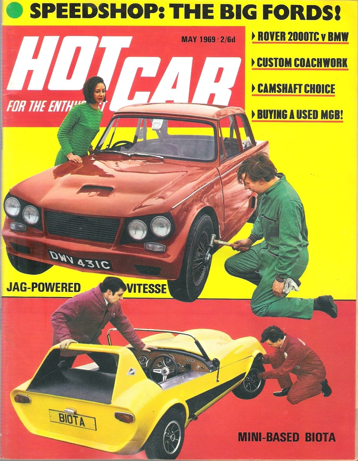
The car was said to do 130mph and to have 250bhp. It was built by the well known Downton engineering. Based on a shortened Jaguar XK150 chassis. The Triumph Vitesse body was altered to fit.


More material about this car featured on Facebook recently.
I recently found an article about the Armstrong Lever Action Shock Absorber as fitted to the Triumph Vitesse and other Triumph cars. The article was on the North American Singer Owners Club website.
The Armstrong New Super Double-Acting Self-Regulating Hydraulic Shock Absorber is of the Vertical Cylinder Type. All working parts are submerged in oil.

The body A is a zinc alloy die casting and bolts directly on to the frame of the car, the two cylinders B and C being connected by passages E and F. The double crank G and arm H are a force fit on serrated portions of spindle I, which rotates in the body A on generous double bearings. Connecting rods J connect the crank G to pistons K to which non-return recuperating valves N are fitted. The arm H is connected to the axle of the car link L.
As the axle moves to and from the car frame, so the pistons move in and out of their respective cylinders pumping oil from one to the other. The interior of the body is filled with oil to within 3/8″ from top of cover, any shortage of oil beneath the pistons is instantly made good though the recuperating valves N.
As the car axle moves to and from the car frame the oil pumped from the compression cylinder B to rebound cylinder C or cylinders C to B, and has to pass between the taper ended valve P and scew Q, which is adjustable to offer any desired resistance to the action of the axle.
As will be seen from the drawing the upper end of the valve F is held in contact with the cam on spindle I, which means that on fairly good roads the valve P is in its lightest setting and shock absorber gives a normal resistance–just enough–yet not too much to produce harshness, but when bad roads are encountered the spindle I oscillates and the contour of the cam depresses the tapered end of valve P further into the central port of screw Q and thereby increases the resistance of the shock absorber.
The automatic, variable resistance obtained from the cam movement makes this shock absorber entirely self-regulating, the resistance automatically increasing as required thus enabling the car to pass over bad with comfort equal to good roads.
As the axle moves towards the frame the oil is pumped from the cylinder B to cylinder C, but as it has to pass the spring loaded valve R a resistance governed by the tension on the spring is offered to the movement of the axle.
On the return or rebound stroke the oil is pumped from cylinder C to cylinder B, and as the ball valve only opens in one direction the oil must now find its way to cylinder B past the taper screw S, which is adjustable to offer any desired resistance to the rebound of the car spring.
Both rebound and compression are controlled by screw Q, to tighten rebound and compression slack nut T, taking care that the screw Q does not turn. Turn screw Q half a turn inwards and lock up the nut, taking care the the screw Q does not turn.
To reduce the resistance follow the above instructions, but turn screw outwards.
Both rebound and compression are controlled by screw S.
The same instructions apply as for cam valve, but refer to screw S and nut U.
Note.–Shock absorbers adjusted too lightly make your car feel harsh and hard; we recommend slacking off first in case of doubt.
These shock absorbers will only work satisfactorily on Armstrong Super Shock Absorber Oil. Examine your shock absorber oil lever regularly. The correct level is 3/8″ from top of cover.
Double Note: I personally have found these shocks to be quite reliable and I have been able to resurect several of these by just general cleaning and fresh oil. You should try that first prior to sending it out for rebuilding.
————————————————
I had heard these existed and have now found a picture. These can be adjusted on the car without taking them apart.
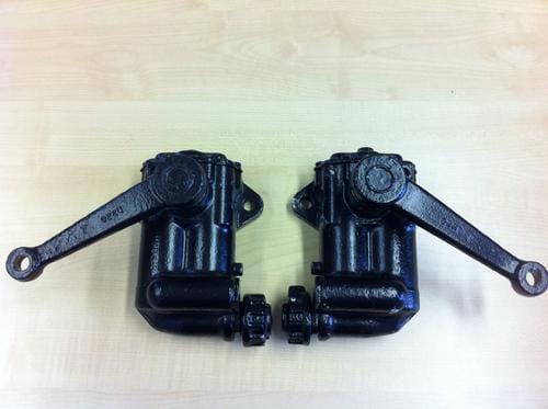 |
| MG works adjustable Armstrong lever dampers |
Period adjustable shock absorbers often feature in accessory catalogues and go faster guides.
Due to the rarity of original adjustable lever arm dampers there are now firms remanufacturing and converting original dampers to be adjustable. One instance is for the MG Sprite with items made in the USA by Peter Caldwell, in Madison, Wisconsin being sold in the UK through http://www.petermayengineering.co.uk/.
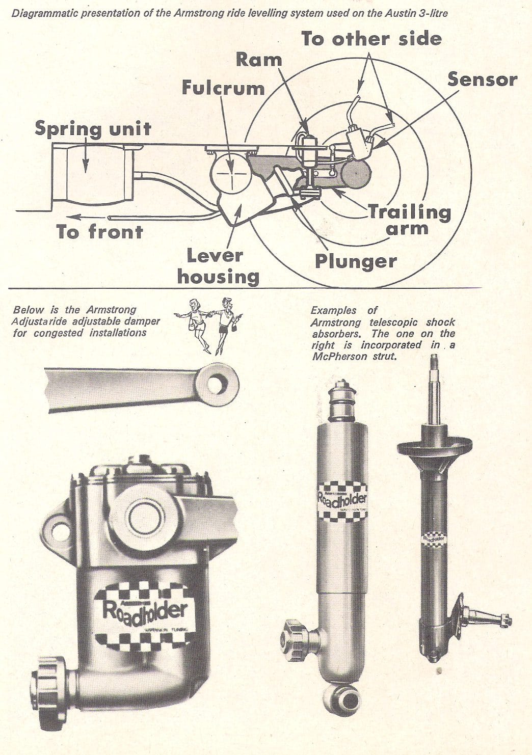 |
| Adjustable Dampers Autocar17 October 1968 |
—————————————————-
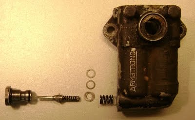
The damper assembly looks as below when assembled:
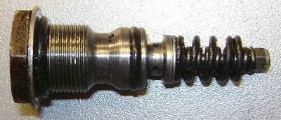 |
| Armstrong lever arm damper assembly |
The little washers between the large diameter coil spring and the valve body set the preload on the BUMP damper valve. So add more washers to get more BUMP damping, try one or two washers at a time, you can easily find washers of similar id and od, if not file some.The little nut that compresses the smaller inner coil spring controls the REBOUND damping. This nut is soldered on its thread to stop it moving, easy to unsolder and resolder. Screw this nut in increases the REBOUND damping. Try one turn at a time, it is quite sensitive.
Do both together, clamp them together in a vice, then by hand pressure on the end of the levers you can compare their resistances to get them both similar.
Refit to car and test. Hours of fun there then!
Borrowed from a Morgan website.
———————————————-
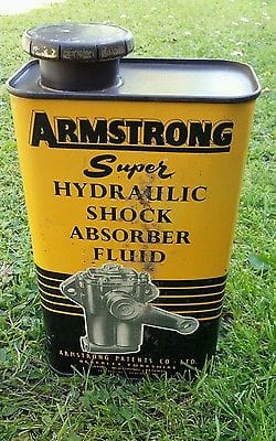
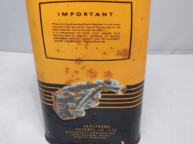
Armstrong sold their own special grade of oil specially for lever arm dampers. What should be used now?
Motor bike shock absorber oil seems to be the recommended substitute. It is available in several different viscosities. 20 as used in older bikes is what can be used. Modern lighter grades will not be stiff enough. Stiffer oil such as 30 may damage the seals.
Some people have successfully used trolley jack oil. However it has been said such oil may suffer from foaming when dampers work hard and quickly – just when you want the damping action.
——————————————————————–
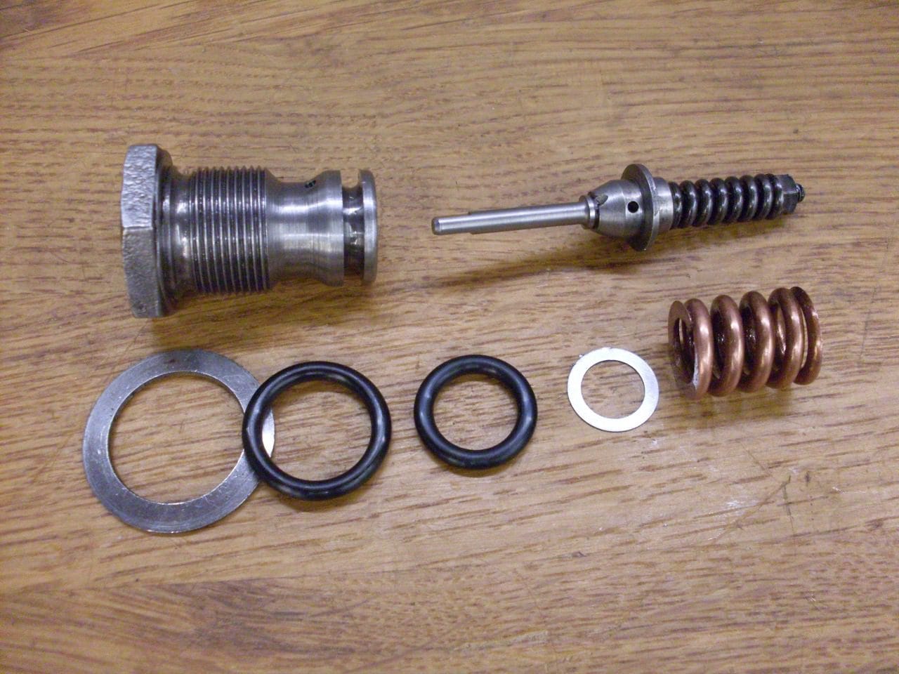 |
| Original Armstrong lever arm damper assembly with o-ring |
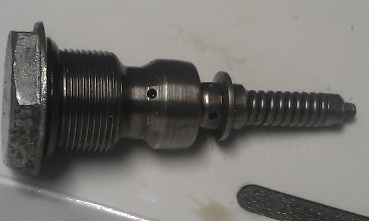 |
| Later simplified Armstrong lever arm damper assembly without o-ring |
According to Alex Pringle on the TR Forum: The old Armstrong Company merged with James Lyon in the early 1970s, and considerable change resulted.
Lever arm shock absorbers, as we think of them, had numerous and varied commercial and industrial applications . . . . automatic door closers being the most often noticed. The old Armstrong company thought of all of these items as appropriate for reconditioning, whereas the new company preferred to simplify (and cheapen) designs – and to abandon reconditioning in favour of straight replacement.
Lever arm shocks manufactured post 1974 or thereabouts were of the simplified variety, until the eventual cessation of mainstream production, towards the end of the decade.
——————————————————

This brochure produced by Armstrong explains the range of Armstrong parts available to tune car suspension. I found this document on the http://mk1-performance-conversions.co.uk/ website a great source for early Mini enthusiast. It shows the optional adjustable dampers available for Triumph cars at the time.
 |
| Armstrong adjustable dampers |
Armstrong adjustable dampers and springs for a works Triumph Spitfire being fettled by Jigsaw classic Triumph specialists. These dampers from the 1960’s were supplied from the collection of David Pearson of Canley Classics.
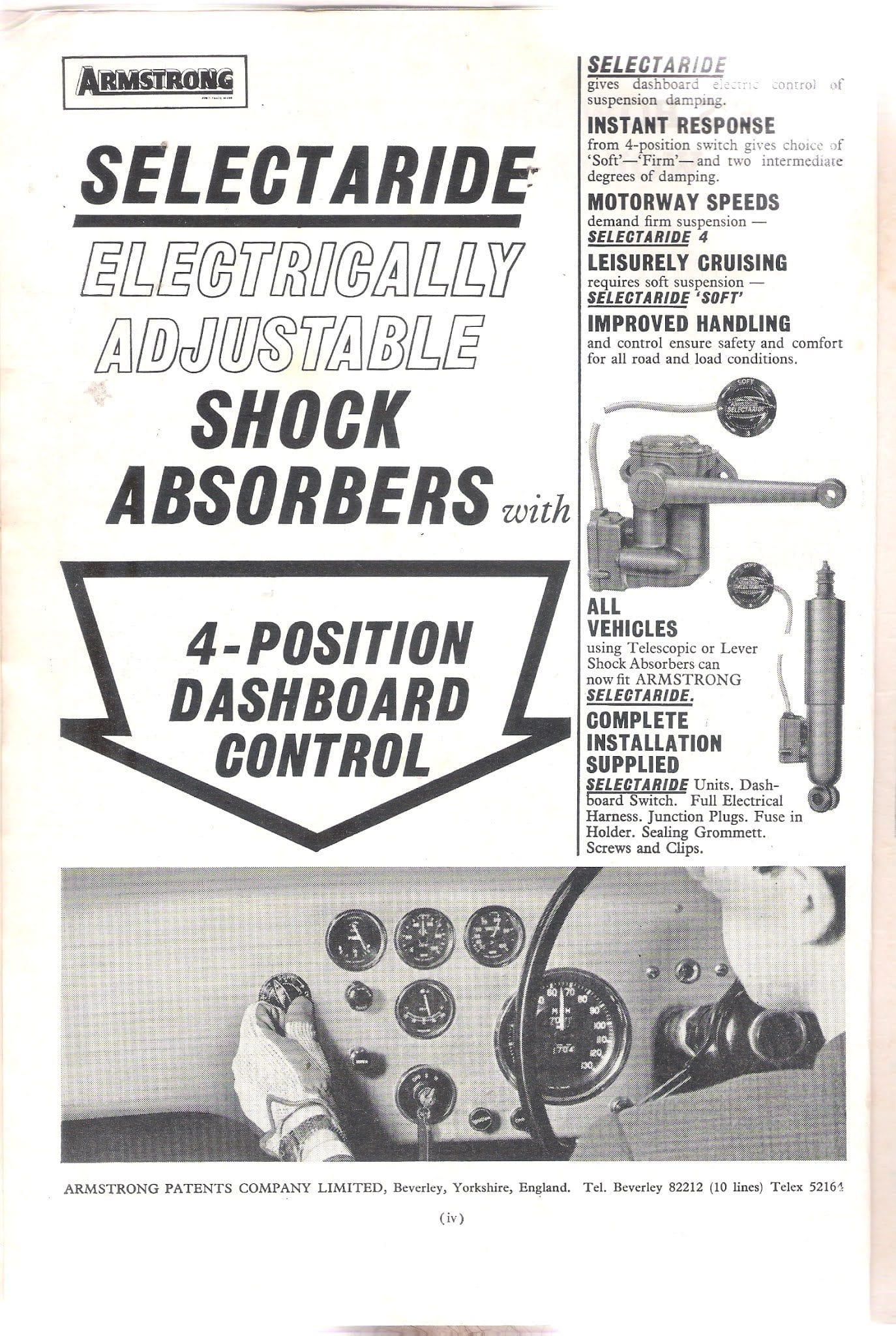
Selectaride electrically adjustable shock absorbers with 4-position “cockpit control”. I think this alternative form of adjustability is interesting.
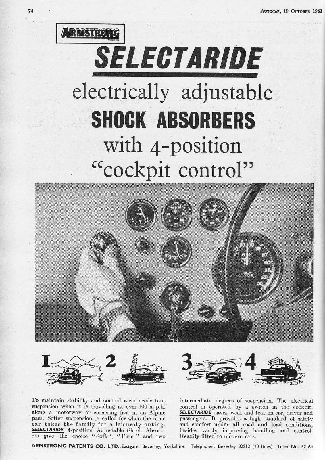
Armstrong marketed electrically adjustable shock absorbers with a 4 position “cockpit control” a switch. These dampers were an ultimately unsuccessful product and were dropped by car manufacturers after they proved to be unsatisfactory in service.
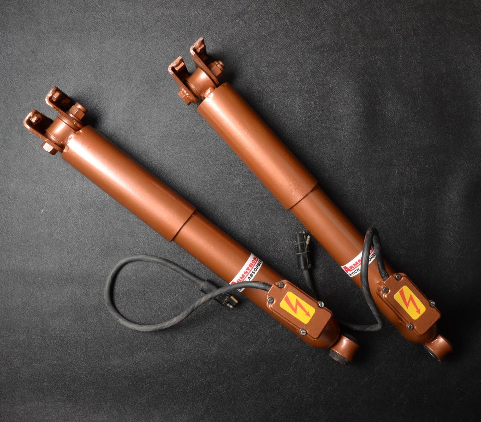
Several companies offer to rebuild your old dampers including marque specialists like racestorations in the UK and Moss in the USA. Additionally firms like Stevson Motors will bebuild units. Stevson has a long history in this field having started out in 1944 from their base in Birmingham UK.
Armstrong dampers were used on many different makes and models of cars over the years. Useful and interesting content can be found found various forums – the TR Register has covered the subject on many occasions.
If you have any information or images you can share to make this article more useful to other readers please get in touch via the comments to this post.
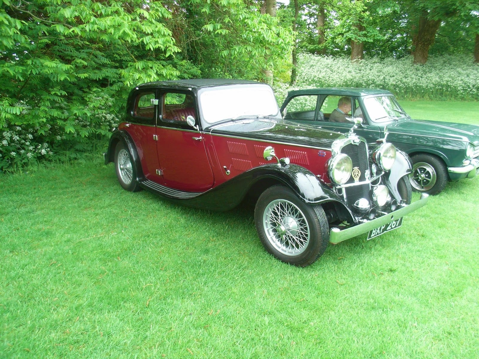
Beautiful Gloria Vitesse parked up at the Club Triumph National at Rockingham Castle. The 1930s Triumphs are great looking.

Triumph Vitesse Mk2 saloon. Good to see a saloon in original condition that has not been converted to a drop head.
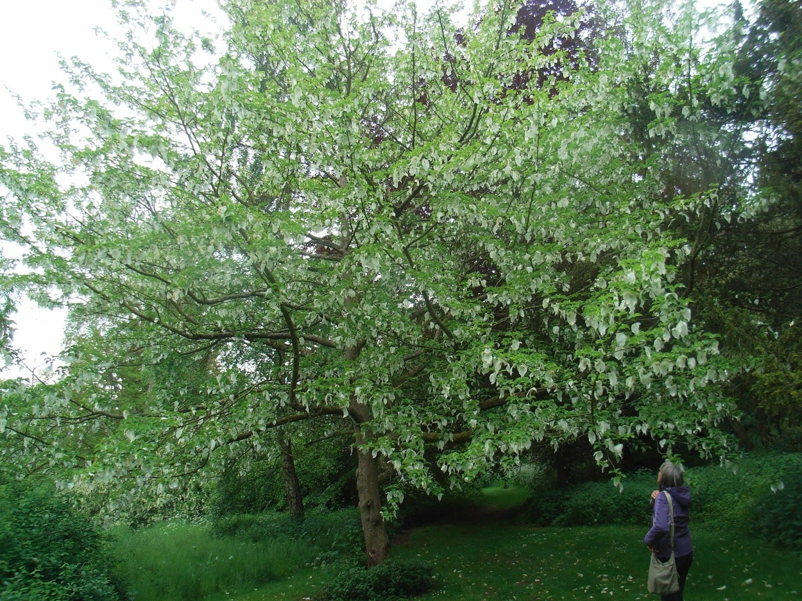
We explored the wild garden at the Castle and saw this Handkerchief tree.
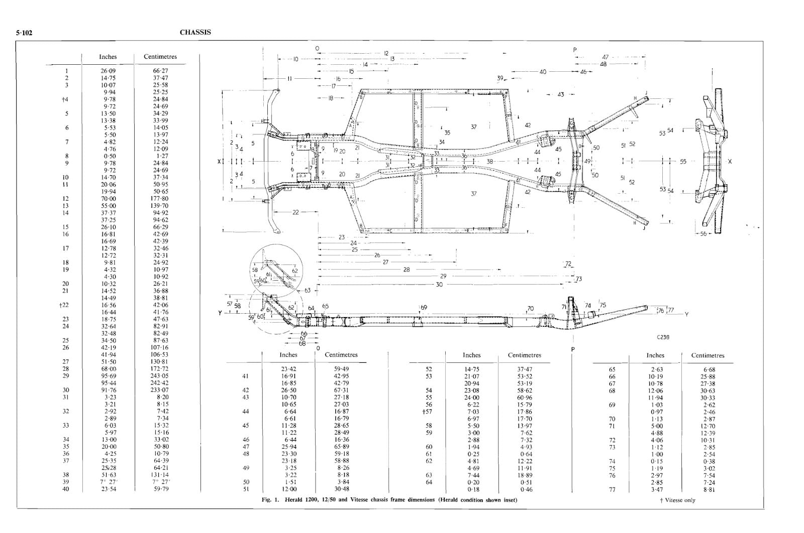
When trying to refit the body to the chassis after some work it is very likely that it will seem to be a difference shape. The number of packaging pieces between the body and chassis may not be the same as when the body was taken off. If any parts of the chassis have been replaced or repaired the shape of the chassis may have changed.
This factory produced guide contains lots of useful pictures and instructions.
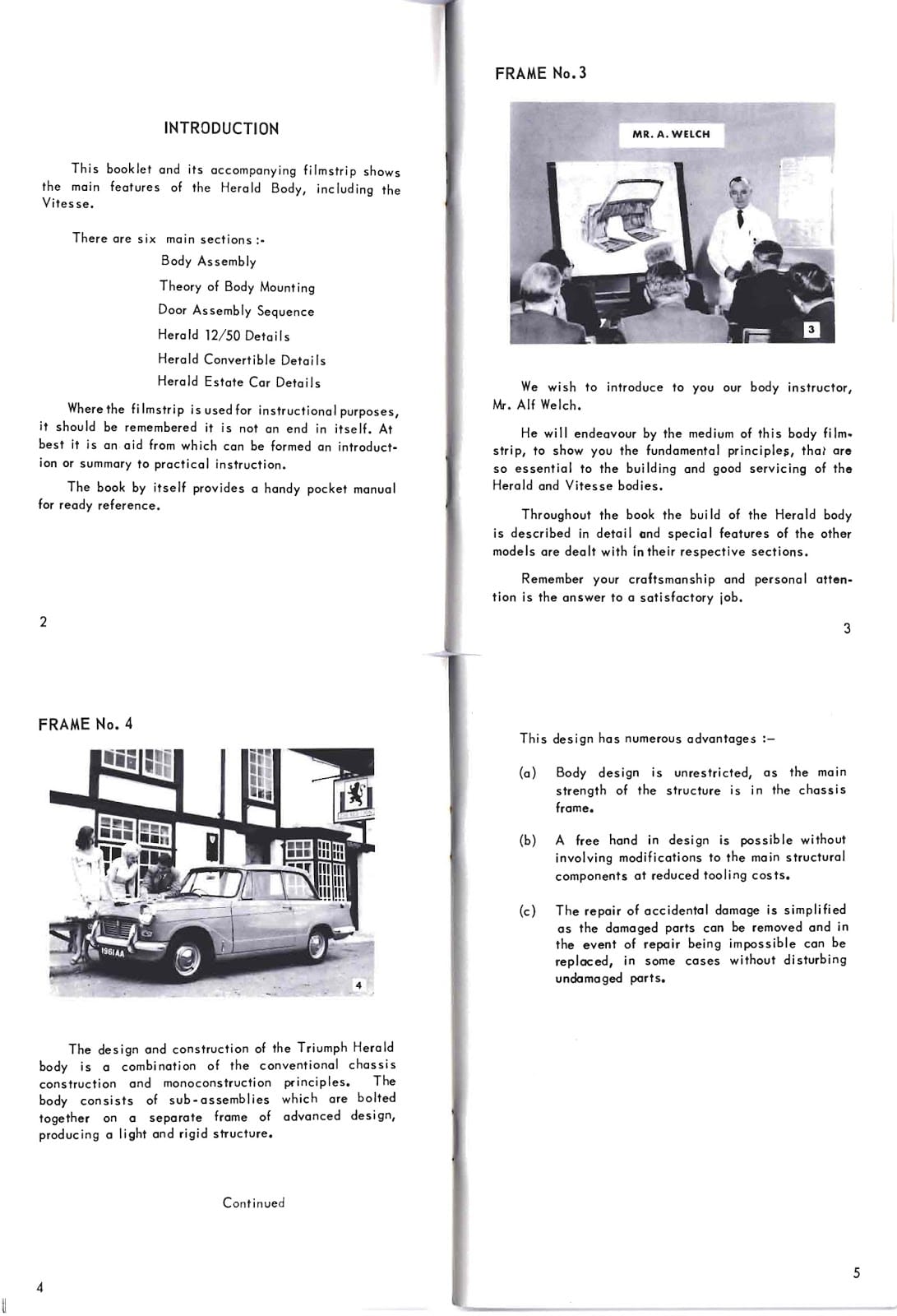
You can get a copy from my website at http://vitessesteve.co.uk/ServiceTrainingNotes
The workshop manual has details of what shape the chassis should be again copy available from my website..
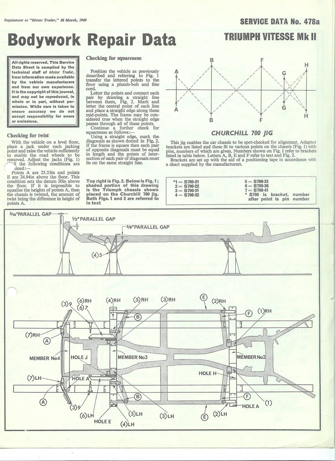
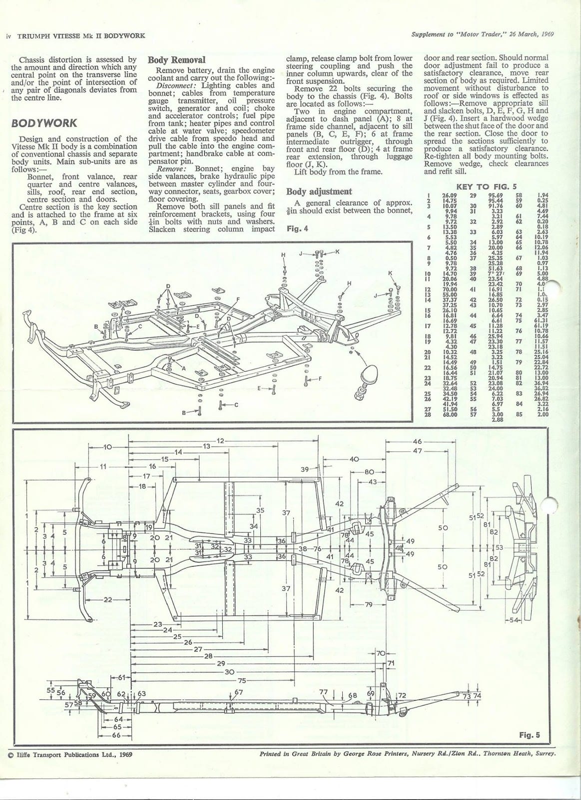
Another source of info about the size and shape of the chassis is the Bodywork Repair Data supplement to the Motor Trader service data for the Triumph Vitesse MkII.
Got the back two done this morning. What a difference turning up first thing on a week day compared with a Saturday morning. No queue so car was sorted quickly. So now have 4 new Vredestein T Trac tyres fitted.
Before buying these tyres I did a little surfiing and found these test results which seem to be all Dutch which I suppose is to be expected for a Dutch tyre maker.
T-Trac
ADAC Motorwelt – 3/2002
Comparative Strengths – Dry Performance
Gute Fahrt – 3/2002
Comparative Strengths – Aquaplaning, Circle Tests
Comparative Weaknesses – Rolling resistance, Comfort
ADAC Motorwelt – 3/2001
Comparative Strengths – Dry Performance
Comparative Weaknesses – Wet Performance, Rolling Resistance
So they should be a good comprimise with strong dry performance possibly at the cost of comfort and economy. I do not drive my Vitesse to save petrol.
I have at last got around to replacing the front tyres on my Vitesse. Had the tracking checked and it was at 7.5 rather than 1.5 toe in. How did it get like that? Normal wear and tear occording to the tyre bay chaps at Selecta Tyre Ltd. 2 Vredestein T-Trac 175/70 for £55.56. Had them inflated with nitrogen just like F1 for an extra £1.25 a tyre. Total with balance and tracking £108.53, not bad I reckon.
I have added a copy of the pdf version of the Vitesse parts manual to my website at: vitessesteve.co.uk/Service%20manuals/Service%20manuals.htm
Should make things easier when trying to order bits from work!